OPTEEQ Programmer Supports Programming CAN-FD Protocol Chips
Overview
With the advancement of technology, the demands of automobile manufacturers for automobile tail lighting systems are becoming more and more diversified. In order to meet the market demand for tail light functions and personalization, more complex LED drive systems have been developed. Existing light drive chips cannot fully adapt to the current electronic and electrical systems. For this reason, Elmos has launched the E522.95 chip that can better adapt to the new market demands.
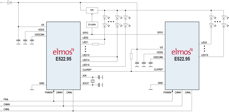
The E522.95 is a multi-channel PWM driver that is connected to the CAN-FD in-car network. The direct connection to the CAN-FD bus enables fast light animation sequences that are controlled by the body controller or the light control unit.
E522.95 chip structure and features
- Fast differential bus interface for dynamic LED control
- Device and LED supply voltage range from 5V to 40V
- 16 PWM generators with 10-bit resolution
- 16 programmable LED drivers, maximum current 100mA
- Direct PWM input
- 10-bit ADC for LED open, short and system diagnostics
- Functional safety ASIL-B level
Programming solution
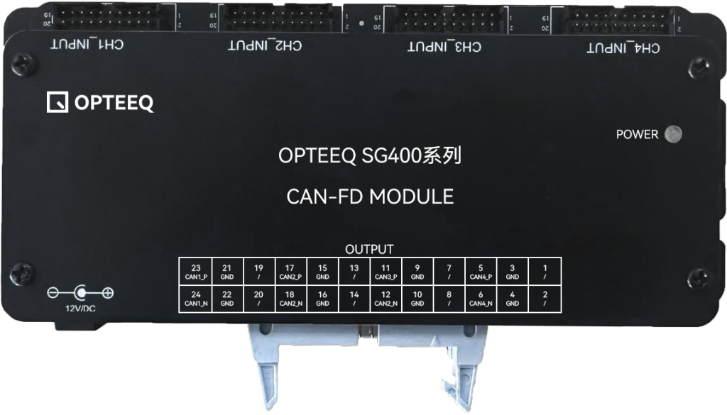
E522.95 uses the CAN-FD protocol with a higher transmission rate. OPTEEQ Technologies provides a solution for programming such chips, which can be realized by adding a “CAN-FD adapter module” based on SG400.
The signal input end of the adapter module is four 2.0-pitch plugs corresponding to the SG400 standard wiring harness. Each plug corresponds to a channel, and each channel works independently; a 12V/DC power input interface is used to power the adapter module; the output interface uses a 24PIN 2.54-pitch ejector header to output CAN-FD signals.
Connection Instructions
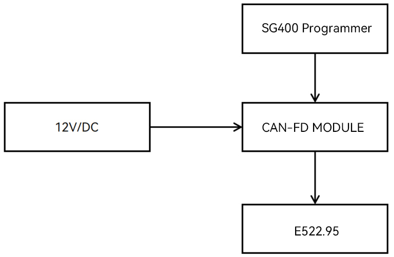
When the adapter module is working, you need to use the standard wiring harness delivered with the SG400 programmer to connect the input interface of the adapter module to the corresponding channel of the SG400 programmer. Use the 24PIN programming wiring harness delivered with the adapter module to connect the output interface to the target chip.
Before connecting the SG400 programmer and the adapter module, please make sure both devices are powered off to ensure the safety of the connection. Please follow the steps below to connect:
- Use the programming cable to correctly connect the SG400 programmer and the adapter module.
- Power on the SG400 programmer and wait for the programmer to start up and run normally.
- Supply power to the adapter module.
*This sequential procedure helps prevent equipment damage or other electrical safety issues caused by incorrect operation.
 Opteeq Technologies丨


Hello!Please log in